Radiographic examination of the digit is the most common radiographic study performed by the equine practitioner. The practitioner should strive to obtain good quality radiographic equipment and develop good radiographic technique. In addition, an accurate diagnosis requires an understanding of good working knowledge of anatomy and pathophysiology of disease. The practitioner needs to understand the complex anatomy of the foot and recognize that there is a range of normal variations seen in many of the anatomical structures in the foot. Good radiographic technique necessitates an understanding of the relationship of limb position, cassette position and x-ray tube angle. It is also important to recognize that inadequate foot preparation, inappropriate projections and motion (of the animal and examiner) can create artifacts. Errors in interpretation often occur due to correctable technical problems.
A detailed clinical exam should be performed before a specific radiographic study can be recommended. The clinical examination should include a complete lameness evaluation with specific manipulative test, flexion tests, and hoof tester application. Ancillary diagnostics such as palmar digital nerve block, distal interphalangeal joint block, navicular bursa block and digital flexor tendon sheath block may further direct the clinical examination. The response to each one of these blocks may direct the clinician to include more definitive radiographic projections. Advanced imaging techniques such as thermography, diagnostic ultrasound, and nuclear scintigraphy can direct the clinician to perform a specific study or to include specific projection to further elaborate an area of interest. In the future, magnetic resonance imaging will become more common but will not preclude the radiographic exam. It is hoped that MR will validate certain radiographic changes seen on the standard foot examination. Radiographic examination of the digit will remain the common imaging technique between the field practitioner and the referral hospital in lameness and prepurchase examinations of the horse.
Equipment
The equine practitioner should develop a working knowledge of the equipment that is currently available. There are a limited number of systems available that meet the requirements of an ambulatory practitioner (MinXray, Medison, Bowie, & Sternes). Most of these manufacturers produce lightweight high frequency units that have greater exposure capabilities. Cost and physical characteristics (weight) of the equipment may influence the suitability of a system for a specific practice. It is preferably to purchase a system with light collimator or laser pointer and a line voltage measuring unit included.
Rare earth systems are of great benefit in radiographic examinations of equine limbs. There are many manufacturers of screens and film (Kodak, AGFA, 3M, MCI OPTONIX). These systems can produce high quality radiographs with portable radiographic systems because they are much faster than traditional calcium tungstate systems. These imaging systems can produce diagnostic images with lower exposure times, which are necessary to minimize motion artifacts and decreases radiation exposure to personnel. The specific imaging system purchased should be based on several factors beyond the scope of this paper but should be influenced by the practitioner?s preference to have a good contrast or good latitude film.
Computed radiography (CR) and direct digital radiography (DDR) have recently been introduced to the veterinary market. There are several systems available and many of these systems have been in use in human medicine for the last decade. These systems can be utilized with the high frequency radiographic systems already in use with current radiographic imaging systems. The major advantage of these systems is that the images have more exposure latitude (more shades of grey) which makes it possible to see both bone and soft tissue detail in the same image. CR & DR systems have the added benefit of software that allows the image to be manipulated (magnification, contrast, brightness, cropping, edge enhancement) as well as allowing the image to be measured and enhanced with drawings. The main disadvantages include cost and the need for specialized training.
Safety equipment that should be incorporated in the production of radiographs include film badges, lead aprons and gloves (.5 mm lead equivalent), and aluminum cassette holders. These safety items are necessary to minimize exposure of personnel to scatter radiation. The holder and horse handler should not be in the primary beam.
Labeling the radiograph
The radiograph is a legal document and part of the permanent medical record for each horse. The legal requirements for maintaining these radiographic studies vary by state and should be determined before discarding any radiograph. In most states the veterinarian is required to maintain the radiographs for 5-7 years. Because many horse owners are keeping horses for longer periods of time it may be advantageous to maintain the radiographs for the life of the horse. The owner?s name, patient name or number, name of the veterinarian or clinic, location of the clinic, date of the examination, and the limb examined (RF, LF, RH, LH) are required. It is helpful to include the specific projection used to generate each specific radiograph. As a rule, the labeling marker should be placed on the lateral and/or dorsal aspect of the plate.
There are several options to label the film but the most common are radio-opaque marking tape with personalized holder blocker and/or light flasher system.
Preparation of the foot
It is essential to clean the foot of dirt and debris before performing a radiographic examination. The bottom of the foot is not the only area that needs to be cleaned but should include the heels and wall. In most instances shoe(s) removal will be necessary to adequately examine the navicular bone and P3 as well as to minimize scatter radiation (which can diminish detail of the radiograph). Skill and the appropriate equipment are necessary to remove the shoes without damaging the foot. Loose flakes of horn from the sole and frog should be pared away and particular attention should be paid to trimming the clefts of the frog sufficiently to allow removal of dirt and debris. Packing the sole and sulci of the frog with a material like Play-do decreases gas artifacts from the trapped air. This packing is especially important for the navicular and P3 examinations. Unfortunately, packing may decrease detail because it adds soft tissue density. Once the foot is prepared it should be placed on paper or canvas to reduce contamination of the packing material with dirt/debris. After the radiographic examination, the foot should be covered with an elastic tape has to prevent the walls from being damaged when traveling from the area of the study to the stall and later to the farrier.
Removal of the shoes is not necessary when performing a podiatry or laminitis study, which is constituted by a 00 Dorsopalmar (DP), & Lateromedial (LM).
Positioning the foot for the examination
Blocks are needed to elevate the foot or feet off the ground allowing the foot to be centered in the cassette and the x-ray beam to pass horizontally through the specific area of interest (i.e. solar surface of the foot, DIP joint, navicular, etc.). The size of the block is dictated by the size of the radiograph machine. The appropriate size block can be determined by measuring from the floor to the center of the collimator and subtract ¾ inch. Ideally the blocks should have two wires embedded in the top of the block which course longitudinally and perpendicular to the first. Two blocks of equal height are needed to allow the horse to bear weight evenly on both feet while performing the radiographic examination(Figure 1). It is important to position the feet on the blocks in a natural position with the cannon bone vertical to the ground, axis of the limb directly under the horse and the foot in line with the conformation of the horse (i.e. if the horse toes in the blocks should be placed in line with the foot direction). The foot should be placed as close the inside of the block when taking a lateral image (to place the cassette as close to the foot as possible on it?s medial surface) to reduce magnification of the subject.
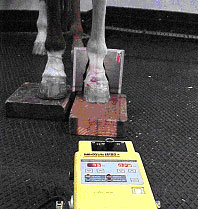
(Fig.1)
Radiopaque markers can be used to assess the exterior surface of the dorsal hoof wall in the radiographic study. Barium paste, wire, or a metallic marker should be placed on the dorsal hoof wall from coronary band to the distal margin of P3 (about ¾ inches from bearing surface) to assess the hoof wall in the lateral view of the foot. Some have used a quarter at the proximal most aspect of the dorsal hoof wall close to the coronary band but this has proven inadequate to assess the distal aspect of the dorsal hoof wall. A thumbtack can be placed in the apex of frog after it has been pared appropriately to determine the position of the true apex of the frog with respect to the distal aspect of P3.
Positioning the X-ray beam
To appropriately position the x-ray beam the veterinarian or technician must have a keen knowledge of the anatomy in the area and a specific area of interest. For instance, to produce the lateral view of the foot, the x-ray beam should be parallel to the bulbs of the heel and centered on the specific area of interest. The navicular bone examination should have the x-ray beam centered below the coronary band midway between the dorsal hoof wall and the heels. The solar surface of P3 will be imaged best by centering the beam ¾? above the distal aspect of the hoof wall at the quarter midway between the heels and the toe.
X-rays obey the inverse square law, which means a small change in focal-film distance (distance between the x-ray machine and the cassette or FFD) can have a significant affect on the exposure (diminishes number of x-rays with distance) (Figure 2). Because a small change in FFD can have a significant effect on exposure, it is imperative that this distance be consistent and should be measured on every exposure. This distance can be measured indirectly in systems with a collimator. The examiner should establish the correct FFD between the machine and cassette and then setting the collimator to the appropriate cassette size. On subsequent exposures the collimator light can then be adjusted to fit on the cassette (provided the cassettes are the same size). It is also possible to place to laser pointers on the x-ray machine that are focused together at the FFD.
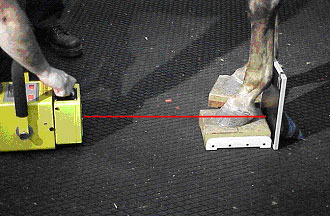
(Fig. 2)
Subject-film distance is also an important variable that should be consistently evaluated and minimized. In most instances, the cassette can be placed as close to the subject as possible. If the plate cannot be placed close to the subject it creates magnification of the subject which reduces image sharpness. Beam angle should be 90 degrees to the cassette whenever possible. When the beam angle varies from perpendicular subject distortion can be a consequence. The subject should also be parallel to the plate to minimize distortion. Remember that the central beam position dictates the area seen with most clarity
Radiographic examination
Standard radiographic study of the foot
Lateromedial
Dorso 65 degree proximal-Palmarodistal Oblique ( D45Pr-PaDiO P3 technique)
Dorso 65 degree proximal-Palmarodistal Oblique (D65Pr-PaDiO navicular technique)
Dorso 45 degree proximal-Palmardistal Oblique (D45Pr-PaDiO)
Palmaro 47 degree proximal-Dorsodistal Oblique (Pa45Pr-PaDiO navicular skyline)
Dorso 0 degree palmar ( D0Pr)
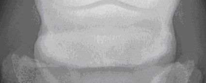
Lateromedial
To obtain a lateromedial radiograph (Figure 3) the foot should be positioned on a block of appropriate size (dictated by the x-ray machine). The foot should be centered in the middle of the cassette. The cassette should be placed as close to the foot as possible. Initially, a survey film should be obtained to include the entire foot and pastern. This is accomplished by centering the beam on the navicular bone which is one centimeter below the coronary band midway between the heels and the dorsal hoof wall. The x-ray beam should be directed parallel to floor centered. If a specific region of interest (previously determined by the clinical exam or advanced imaging techniques) has been determined then the x-ray beam should be directed at this site. Typically, the x-ray beam position varies between the solar surfaces of P3 (½ to ¾ inch above bearing surface of the foot for podiatry and laminitis studies) to more proximally at the coffin joint/navicular bone (beam centered at the middle of the coronary band). The beam angle should pass parallel to the bulbs of the heel. The radiograph demonstrates the dorsal and palmar aspect of P3 and the end on view of the navicular bone. With appropriate technique the dorsal hoof wall should be apparent with most normal horses having a thickness 15-18 mm (for most breeds). The proximal and distal border as well as the contour of the flexor surface of the navicular should be easy to discern when the projection is centered at this area.
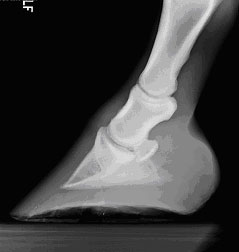
(Fig. 3)
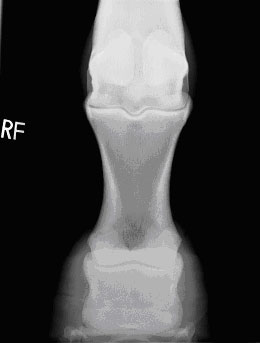
Dorso 65 degree proximal-Palmarodistal Oblique
The dorso 65 degree proximal-palmarodistal oblique (Figure 4) can be obtained with the foot in a weight-bearing position or with the foot on a navicular block (upright pedal). For the weight-bearing technique the foot is placed on a tunnel to the front of the cassette and the beam is directed 65 degree to the floor. With this technique the beam is directed 2 cm proximal to the coronary band. For the upright pedal the foot is placed on a block that holds the cassette while allowing the foot to be placed such that the toe is 85 degrees to the ground surface. This allows the x-ray beam to be directed horizontal with the ground centered 2-3 cm proximal to the coronary band on midline. The cassette is placed as close to the solar surface of the foot. The upright pedal view creates less distortion than the weight-bearing technique. This oblique is utilized because of good visualization of the body, solar margin and palmar processes of the distal phalanx.
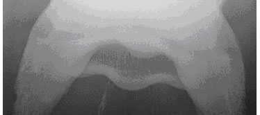
This same projection can be modified to evaluate the navicular bone (Figure 5). Two different views can be used to aid interpretation and differentiate artifacts. The navicular technique should have the beam collimated so that navicular bone is the primary area of interest. Most radiologists recommend the use of a grid (6:1 preferable but 8:1 acceptable). Because this view of the navicular bone is especially susceptible to artifacts it is necessary to thorough cleaning and packing of the foot. The margin of P3 can be difficult to assess if the technique is not appropriate. This projection of the navicular bone provides the examination of the wings and body of the navicular bone as well as the proximal and distal borders.
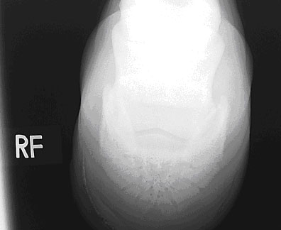
(Fig. 4)
(Fig. 5)
Dorso 45 degree proximal-Palmardistal Oblique
The foot is placed on a block of appropriate size. For this projection it is necessary to have a 45 degree slot cut into the block to accept the cassette. The horse should stand with the bulbs of the heel placed as close to the cassette as possible to prevent unnecessary magnification of the digit. This technique typically provides poor detail of P3 and the coffin joint but does provides a good assessment of the proximal border of the navicular bone. Good to evaluate the DIP joint, collateral cartilages, axis of the digit and the proximal border of the navicular bone (Figure 6)
(Fig. 6)
Palmaro 45 degree proximal-Dorsodistal Oblique
The foot is placed on a tunnel which is placed behind the opposite limb. The foot positioned as far caudally on the tunnel as possible. The horse should have the majority of it?s weight placed on the front limb. The x-ray machine should be placed above the foot close to the thorax of the horse. The x-ray beam should make an angle parallel with the flexor cortex of the navicular bone (approximately 45-47 degrees). Foot conformation can influence the beam angle by affecting the flexor surface angle. Some clinicians take and develop the lateral view first to determine the correct angle. It is important to not superimpose the fetlock over the heels. The beam should be centered on the bulbs of the heel. This oblique projection of the navicular bone allows assessment of the flexor cortex, medullary cavity and flexor surface of the navicular bone as well as the palmar/plantar processes of the distal phalanx (Figure 7).
(Fig. 7)
Dorso 0 degree palmar
The foot should be placed on the appropriate sized block to allow the correct beam position. When performing the podiatry examination the DP projection should have the beam horizontal (parallel) and centered ½ to ¾ inch above the bearing surface of the foot. The plate should be placed as close to the bulbs of the heels as possible. The beam should be raised if the navicular region is the primary area of interest bone (coffin joint, navicular) in the DP plane (Figure 8).
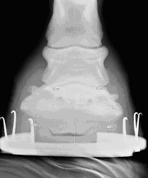
(Fig. 8)